

Have you ever been frustrated by errors and delays in CNC machining? Without a clear understanding of the machining process and material characteristics, you may encounter issues such as low production efficiency, increased costs, and subpar quality. These problems not only waste resources but can also damage customer trust and lead to lost orders. By choosing a professional CNC machining service provider, you can ensure precise machining, improve efficiency, avoid unnecessary headaches, and streamline your production process.
Before starting CNC machining, it's crucial to understand the operational processes, material characteristics, and how they match with the machining technology.

Here's a detailed analysis:
Basics of CNC Machines
What is a CNC Machine and How Does it Work?
A CNC machine (Computer Numerical Control machine) is an automated device that controls the machining process through computer programs. Its working principle involves converting design blueprints into CNC commands, which the CNC system uses to control the machine and carry out high-precision, high-efficiency machining. The CNC system typically receives commands like G-code and M-code to control the movement of machine axes and accurately manage tool paths and cutting parameters to complete part machining.
The basic operation of a CNC machine can be divided into two steps:
- Input Programming Instructions: Designers use CAD/CAM software to convert product designs into CNC instructions.
- Execute Machining: The CNC system follows these instructions to perform various machining operations, such as drilling, milling, turning, etc.
This precise control has made CNC machines a cornerstone of the manufacturing industry, particularly for high-precision, mass-production applications.
Key Components of CNC Machines
CNC machines consist of several key parts:
- CNC System: Responsible for processing commands and controlling machine operations. Common CNC systems include FANUC and Siemens.
- Servo Motors and Drive Systems: Control the motion of the machine’s axes.
- Feed Drive Systems: Convert the movement from servo motors into mechanical motion, driving various machine components.
- Tools and Tool Changers: Cutting tools for machining, with tool changers storing multiple tools.
- Worktables and Fixtures: Used to secure and position workpieces.
- Cooling Systems: Provide cooling and lubrication during machining.
These components work in tandem to ensure the machine operates efficiently and stably, delivering precision machining.
Common Machining Methods and Applications
CNC machines can perform various types of machining, including:
- Milling: Rotating tools cut the workpiece surface, widely used for metal, plastic, and other materials.
- Turning: Workpieces rotate while tools move relative to them, ideal for cylindrical parts.
- Drilling: Making holes in the workpiece, commonly used for manufacturing mechanical components.
- Grinding: Using abrasives to perform precision surface finishing, suitable for high-precision parts.
- EDM (Electrical Discharge Machining): Uses electrical discharges to cut metal, commonly used for hard alloys and complex shapes.
These machining methods find extensive use in industries like aerospace, automotive, and medical devices.

CNC Programming
Basics of G-Codes
G-code is the most commonly used programming language for CNC machines, specifying machine movements, speeds, feeds, and other machining parameters. ISO 6983 G codes and M codes:
G-Codes (Function Codes)
| G Code | Meaning |
|---|---|
| G00 | Rapid positioning (non-cutting) |
| G01 | Linear interpolation (cutting) |
| G02 | Clockwise circular interpolation (cutting) |
| G03 | Counterclockwise circular interpolation (cutting) |
| G04 | Pause (delay) |
| G05 | High precision control |
| G06 | High-speed interpolation |
| G07 | Circular interpolation conversion |
| G08 | Cancel circular interpolation |
| G09 | Exact stop |
| G10 | Data input |
| G11 | Cancel G10 settings |
| G12 | Clockwise circular interpolation (tool radius compensation) |
| G13 | Counterclockwise circular interpolation (tool radius compensation) |
| G14 | Tool compensation increment |
| G15 | Tool compensation return to zero |
| G16 | Cutting direction control |
| G17 | XY plane selection |
| G18 | ZX plane selection |
| G19 | YZ plane selection |
| G20 | Use imperial units |
| G21 | Use metric units |
| G22 | Enable circular compensation mode |
| G23 | Cancel circular compensation mode |
| G24 | Tool path calculation method |
| G25 | Coordinate range check |
| G26 | High-speed feed mode |
| G27 | Machine coordinate system check |
| G28 | Return to machine origin |
| G29 | Return to previous specified point |
| G30 | Return to second home position |
| G31 | Probe mode |
| G32 | Turning feed mode |
| G33 | Automatic thread cutting |
| G34 | Automatic variable pitch thread cutting |
| G35 | Automatic progressive tool cutting |
| G36 | Thread cutting |
| G37 | Automatic tool length measurement |
| G38 | Automatic tool radius measurement |
| G39 | Adaptive tool compensation |
| G40 | Cancel tool radius compensation |
| G41 | Tool radius compensation left |
| G42 | Tool radius compensation right |
| G43 | Tool length compensation positive value |
| G44 | Tool length compensation negative value |
| G45 | Tool radius compensation increment |
| G46 | Tool radius compensation decrement |
| G47 | Incremental compensation left tool radius |
| G48 | Incremental compensation right tool radius |
| G49 | Cancel tool length compensation |
| G50 | Tool compensation reset |
| G51 | Expanded feed rate |
| G52 | Workpiece coordinate system transformation |
| G53 | Machine coordinate system |
| G54-G59 | Work coordinate system selection |
| G60 | Exact positioning |
| G61 | Exact stop mode |
| G62 | Automatic pause mode |
| G63 | High-speed drilling mode |
| G64 | Standard machining mode |
| G65 | Call macro program |
| G66 | Call macro program and pause |
| G67 | End macro program call |
| G68 | Coordinate axis rotation |
| G69 | Cancel coordinate axis rotation |
| G70 | Finishing cycle |
| G71 | Rough machining cycle |
| G72 | Slightly finishing mode |
| G73 | High-speed milling cycle (deep hole drilling) |
| G74 | Left-hand tapping cycle |
| G75 | Turning automatic cycle |
| G76 | Automatic finishing cycle |
| G77 | Finishing mode |
| G78 | Finishing mode |
| G79 | High-precision machining mode |
| G80 | Cancel machining cycle |
| G81 | Simple drilling cycle |
| G82 | Drilling cycle (with pause) |
| G83 | Deep hole drilling cycle |
| G84 | Tapping cycle |
| G85 | Boring cycle |
| G86 | Turning hole machining cycle |
| G87 | Gear cutting cycle |
| G88 | Turning self-loop cycle |
| G89 | Drilling cycle (with pause and feed) |
| G90 | Absolute coordinate programming |
| G91 | Incremental coordinate programming |
| G92 | Fixed position programming |
| G93 | Reverse feed mode |
| G94 | Feed rate per minute |
| G95 | Feed rate per revolution |
| G96 | Constant cutting speed |
| G97 | Return to normal spindle speed |
| G98 | Return to initial point |
| G99 | Return to R point |
M-Codes (Program Control Codes)
| M Code | Meaning |
|---|---|
| M00 | Program stop |
| M01 | Optional stop (optional program stop) |
| M02 | Program end |
| M03 | Spindle clockwise rotation |
| M04 | Spindle counterclockwise rotation |
| M05 | Spindle stop |
| M06 | Tool change |
| M08 | Turn on coolant |
| M09 | Turn off coolant |
| M10 | Clamp closing |
| M11 | Clamp opening |
| M12 | Set processing program |
| M13 | Machine start |
| M14 | Automatic tool change |
| M15 | Spindle control |
| M16 | Return to origin |
| M17 | Motor enable |
| M18 | Motor disable |
| M19 | Spindle orientation |
| M20 | Cancel pause |
| M21 | Workpiece detection |
| M22 | Automatic tool setting |
| M23 | Automatic tool measurement |
| M24 | Return to machine start point |
| M25 | Spindle stop |
| M26 | Switch cutting mode |
| M27 | Enable external device |
| M28 | Stop external device |
| M29 | Auto start |
| M30 | Program end and reset |
The above G and M codes are based on ISO6983 standards. However, depending on the operating system, there may be variations. Be sure to consult the system manual before implementation.
Structure and Format of CNC Programs
A typical CNC program consists of the following sections:
- Program Header: Contains basic program information, such as program number and name.
- Initialization Commands: For unit selection, tool setup, etc.
- Machining Commands: Includes G-codes and M-codes, directing the machine to perform specific machining tasks.
- Program End: Contains end commands, typically signaling the end of the program.
CNC programs must adhere to specific formats to ensure the machine executes tasks smoothly.

Machining Processes
Basic Concept of Machining Processes
A machining process refers to the entire sequence of steps followed to shape raw materials into finished products. This includes selecting the appropriate machining method, determining machining parameters, and choosing tools and fixtures to achieve the desired machining quality.
Common Machining Methods
Common machining methods include:
- Milling: Rotating tools cut the workpiece.
- Turning: A combination of workpiece rotation and tool movement for cutting.
- Drilling: Cutting holes using a drill bit.
- Grinding: Precision finishing of workpieces using abrasives.
Each method has its unique advantages and disadvantages, and the choice depends on the material, shape, and size of the workpiece.
Fixtures and Positioning
Fixtures are tools used to secure and position the workpiece. They play a critical role in machining accuracy and efficiency. Common types include mechanical and pneumatic fixtures. The accuracy of positioning directly affects the machining precision, so selecting the right fixture and positioning method is crucial.
Process Optimization and Efficiency Improvement
Optimizing the machining process can enhance productivity and machining quality. Common optimization strategies include choosing the right tools, reducing tool change times, and increasing feed rates. Process optimization can also reduce costs and improve a company's competitiveness.
Tool Selection and Usage
Choosing the right tool is essential for machining accuracy, surface quality, and cutting efficiency. Factors like material, coating, shape, and size affect machining results. Selecting the right tool and adjusting its usage conditions based on the machining requirements can significantly boost efficiency.
Materials and Cutting
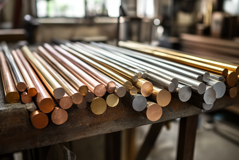
Basic Material Properties and Classification
Selecting the right material is critical in CNC machining. Common materials include metals (steel, aluminum, copper), non-metals (plastics, ceramics), and composite materials. Different materials have distinct physical and chemical properties, so the appropriate machining method must be selected based on material characteristics.
Cutting Characteristics of Common Materials
The cutting characteristics of materials differ, influencing tool selection and cutting parameters. For example, aluminum alloys are easy to cut and are suited for high-speed machining, while steel requires lower cutting speeds and high-strength tools.
Aluminum Alloys
Aluminum alloys are relatively easy to cut, with low density and hardness, making them suitable for high-speed machining. Key cutting characteristics include:
- High cutting speed: Due to aluminum's lower hardness, high cutting speeds (300-500 m/min) can be used, improving production efficiency and reducing cutting forces.
- Low cutting force: Aluminum alloys generate less cutting force, resulting in lower tool wear and longer tool life.
- Good surface finish: Aluminum's low hardness and excellent plasticity lead to smoother surfaces with minimal machining marks.
- Good thermal conductivity: Aluminum’s thermal conductivity helps dissipate heat, reducing tool wear.
Tool Selection:
For aluminum, high-speed steel or carbide tools are commonly used. Tools with wide edges are preferred to improve cutting performance and surface quality.
Cutting Parameters:
- Cutting speed: High, typically between 300-500 meters per minute.
- Feed rate: Higher feed rates improve efficiency.
- Cutting depth: Generally 1-3 mm for shallow cuts.
Steel
Steel, including carbon steel, alloy steel, and stainless steel, is harder and stronger than aluminum, making its cutting characteristics more complex. Key cutting characteristics include:
- High hardness: Steel generates high cutting forces, causing more tool wear, which requires stronger tools.
- High cutting temperature: Steel has poor thermal conductivity, so cutting generates more heat, risking tool overheating.
- Large cutting forces: Steel requires higher machine stability, especially during deep cuts.
- Rougher surface finish: Steel can result in a rougher surface compared to aluminum, requiring higher precision machining.
Tool Selection:
Hard carbide or coated tools are commonly used for steel to withstand high temperatures and maintain durability.
Cutting Parameters:
- Cutting speed: Lower, typically between 50-150 meters per minute to prevent excessive tool wear.
- Feed rate: Moderate, with a balance between stability and productivity.
- Cutting depth: Usually 2-5 mm, shallow cuts are recommended for hard steel.
CNC Machine Operation and Maintenance
Operating a CNC Machine: Key Considerations
When operating CNC machines, it’s crucial to pay attention to safety, precision control, and program accuracy. Adhering to operational procedures ensures no machining errors or safety incidents.
Daily Maintenance and Care
Routine checks, cleaning, and lubrication are essential to maintain long-term machine stability. Electrical, hydraulic, and servo systems should be regularly inspected, and worn components should be replaced promptly.
Precision Checks and Calibration
To ensure machining precision, the machine must undergo regular checks and calibration. Using standard gauges to verify position accuracy, repeatability, and other parameters ensures consistent machining quality.

FAQ:
- What are the types of CNC machines used in machining?
There are several types of CNC machines, including CNC mills, lathes, routers, and EDM machines. Each has specific applications based on the part’s complexity, material, and precision requirements.
- How does CNC machining affect production speed?
CNC machining significantly boosts production speed due to its automation and precision. This results in faster turnaround times, less human error, and more consistent output.
- What is the importance of tolerances in CNC machining?
Tolerances determine the allowable limits of variation in a part’s dimensions. Tight tolerances are crucial for parts requiring high precision, impacting the functionality and quality of the finished product.

Conclusion
By understanding the CNC machining process, technologies, and material characteristics, you can better collaborate with CNC machining service providers to ensure a smooth production process. Whether it’s selecting the right material, optimizing machining techniques, or ensuring equipment maintenance and precision calibration, careful consideration is key. For businesses seeking high-precision, high-quality products, choosing an experienced CNC service provider is critical. At PROMACHINED, we don’t just offer professional custom machining services—we focus on detail and precise delivery in every project, ensuring the highest standards from start to finish.
